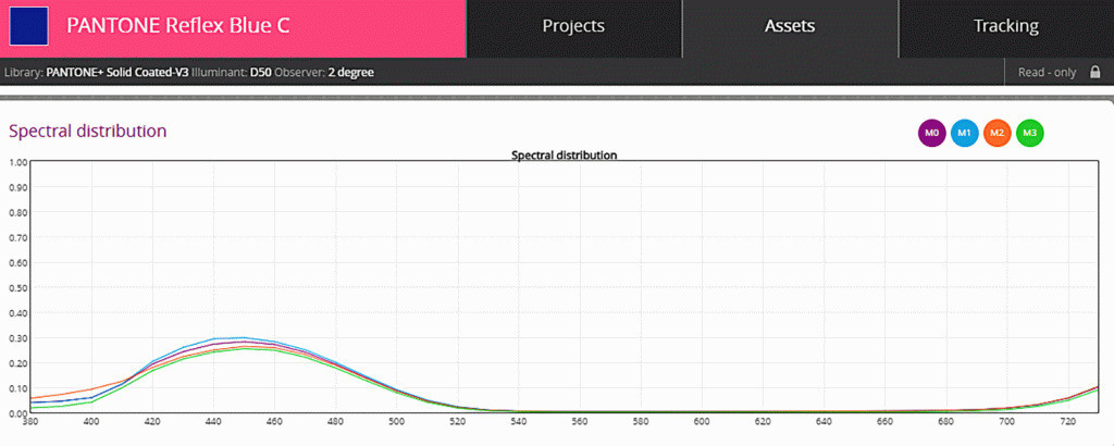
When measuring color from printed materials with a spectrophotometer, choosing the right measurement mode is crucial to getting accurate, meaningful, and shareable results. Most instruments offer several modes, designated M0, M1, M2, and M3. Here's the single most important thing to understand up front: these modes are defined by the UV content of the instrument's illumination — not by gloss, not by finish, and not by which color space you're computing in. They exist because optical brightening agents (OBAs) in paper fluoresce under UV light, and without a defined UV condition, two instruments will read the same sheet differently. These conditions are specified in ISO 13655. M0 is the legacy mode. It uses a light source approximating CIE Illuminant A (historically a gas-filled tungsten lamp) with no defined or stable UV content. Best for: substrates with no optical brightening agents, printed with conventional non-UV inks. Since a non-OBA substrate doesn't fluoresce, M0 captures its color without interference. The catch: because M0's UV content is undefined, two M0 instruments from different manufacturers can read the same fluorescing sheet differently. ISO 13655 specifically does not recommend M0 when the sheet exhibits fluorescence and you need to exchange data between facilities. From a purely technical standpoint, M0 is now considered obsolete for most graphic arts work. M1 uses a light source simulating illuminant D50 with a correctly specified UV component. It was defined to reduce the variation between instruments caused by fluorescence — whether from optical brighteners in the paper or from fluorescing colorants. Best for: substrates containing OBAs, which is most modern paper. Because M1's UV content is matched to D50, brighteners "glow" during measurement roughly the way they will in a D50 viewing booth — so your numbers actually correspond to what people will see. M1 is the required measurement mode for submitting G7 data to Idealliance for the GRACoL 2013 print specification. If you take one thing from this article: for most modern print work, M1 is the answer. ISO 13655 defines two routes to M1 compliance. Part 1 is a full D50 spectral match, valid where either substrate or colorants may fluoresce. Part 2 addresses the case where the substrate fluoresces and its brightener response needs capturing, but you're confident the imaging colorants do not fluoresce. (If you're unsure, ask your ink manufacturer.) M2 was standardized to define what UV exclusion means in a measuring instrument — variously called UV-cut, No-UV, or UV-filtered. The illumination contains essentially no energy below 400 nm. Best for: situations where the paper fluoresces but you want that effect removed from the data. It simulates a viewing environment with no UV content — a museum, for instance. M2 is generally preferred for measuring UV inks, because eliminating UV from the illumination removes fluorescence effects that would otherwise distort the reading. M3 takes M2's UV-restricted illumination and adds a polarizing filter (a crossed pair, in the emitted and reflected light). Best for: minimizing first-surface reflections. That makes it valuable for wet press sheets, metallic inks, and materials with a glossy, transparent, or heavily textured surface — textiles, films, backlit and transparent media, and plastics. What polarization does: it reduces or removes the specular reflections coming off the surface, so the measurement reflects the color of the material rather than the shine on top of it. This is a surface-reflection control — it does not address metamerism, which is a different problem entirely. In principle the decision is clean: The one rule that matters most in practice: don't mix modes. A proof verified in M1 and a press sheet read in M0 are not comparable numbers, no matter how confidently either party quotes them. It's equally important to consider your viewing conditions, and whether UV is present in them. UV light "activates" optical brighteners. Compared against a substrate with no OBAs, that can produce a very noticeable color difference — and it's why ISO 13655 (measurement) and ISO 3664 (viewing) have to be considered together. Your instrument and your light booth need to agree. Not sure which mode your workflow should be standardized on — or whether your instrument and light booth agree? That's exactly the kind of thing we sort out. Lead Color Specialist, Alder Color Solutions Bill is an Idealliance-certified G7 Expert and founder of Elevated Color, with more than 45 years in prepress, printing, and color management — including over 25 years dedicated to helping printers achieve predictable, repeatable color across commercial, packaging, wide-format, offset, digital, and inkjet work. He specializes in G7 implementation, ICC profiling, press and monitor calibration, proofing systems, and workflow standardization, with deep experience across RIPs including EFI Fiery XF, PrintFactory, ChromaChecker, Onyx, Caldera, and Xitron Navigator, and platesetter workflows such as Agfa Apogee, Kodak Prinergy, Esko, and Heidelberg Prinect. His work has appeared in PRINTING United, Idealliance, and WhatTheyThink.Quick Reference: The Four Modes
Mode
Illumination
Use it for
M0
Illuminant A (tungsten), undefined UV
Legacy workflows; substrates and inks that don't fluoresce
M1
D50, UV included
Substrates with OBAs. Required for G7 / GRACoL 2013. The modern default.
M2
UV cut (UV excluded)
Removing OBA fluorescence from the data; UV inks
M3
UV cut + polarizing filter
Minimizing surface reflections — wet press sheets, metallics, textiles, films, plastics
M0 — Legacy / Illuminant A
M1 — D50, UV Included
M2 — UV Cut
M3 — Polarization
Which Mode Should You Use?
A Note on Viewing Conditions
Schedule a Consultation
billo@aldertech.com — 720-933-4413About the Author

Bill Owen
Phone: 720-933-4413